How to build a computer – Phase 2: Assembling
This is the second article of a series: how to build a computer. For the first post click here. In this article we’ll speak about putting the pieces together: assemble!
Important: I take absolutely NO responsibility of what you do. Know, that working with electricity may cause fatal accidents and fire, so be careful.
First step: precautions!
The first thing you got to do is operate cautiously, depending on your actions you might damage components, yourself, or your house. During the assembling process follow these guidelines to avoid nasty consequences:
- Never touch your PC while it is powered.
- Do not operate in dim light and/or dusty places.
- Do not use water or liquids near the PC while building.
- Always double-check connections before powering up.
Another rule of thumb I have is to avoid plugging in the power supply in the power outlet before I have finished building everything. For newbies, I also suggest to close the case before powering up. Now let’s introduce another important practice: grounding. With this term we refer to the action of discharging a body of static electricity that might damage sensible components. To ground yourself, simply touch a metal surface. Another option is to buy an anti-static wrist strap, which is good to have, however it is not required since you can simply ground yourself how many times you want. Now we can get started. Before anything else, let’s emphasize this: read the manuals. Manuals contain the most accurate information for your pieces. If you’re in real trouble, ask on the Internet, but don’t forget manuals will most likely cover your doubts.
Step two: open the case & mount the motherboard
The first step is to open the case. To mount the motherboard, the usual piece to remove is the left panel (if you’re watching your case from the front). Specific cases may have different assets, but usually it will be the left panel. The right panel is usually left attached during the whole process process however, some cases might require you to remove the right panel to install disks or drives. Once you’ve opened the case look for the place where the motherboard will reside. Tip: you can easily find it by looking at screw holes. Now look up in the manual where to place the standoff screws, depending on which form factor your motherboard has.
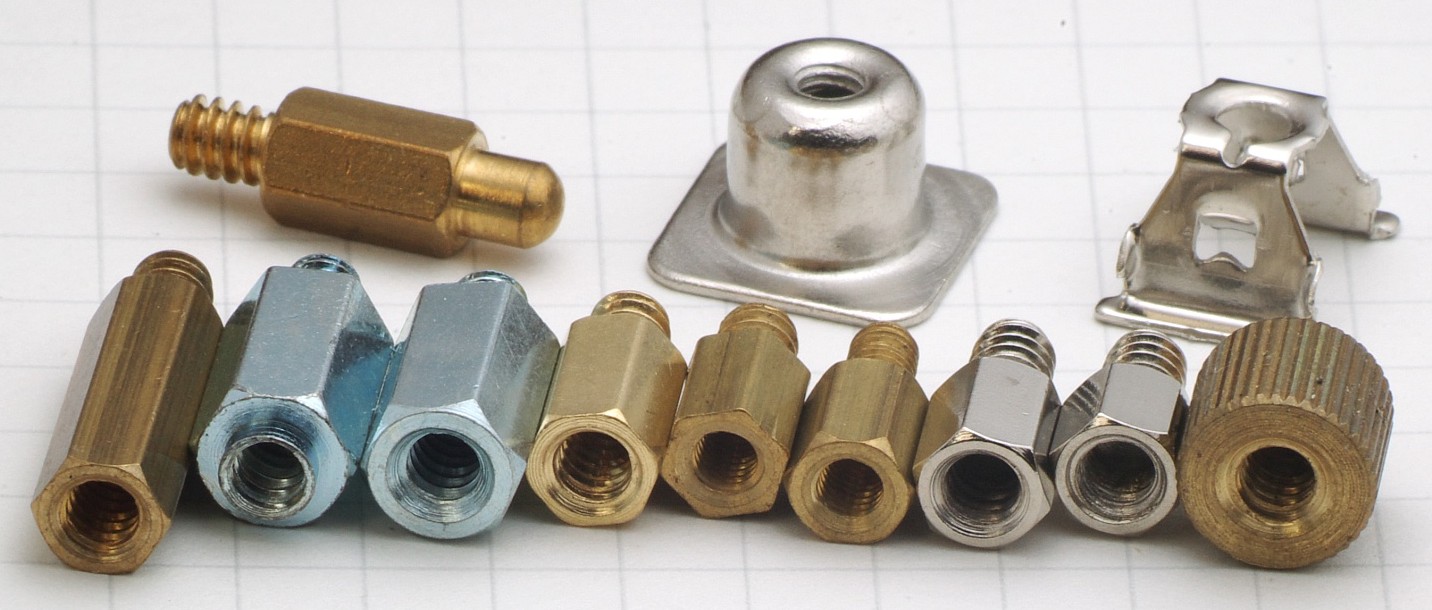
By Smial (Own work) [FAL or GFDL 1.2], via Wikimedia Commons
Step three: mount the processor
The processor is the most delicate part of the computer, be careful when managing it. Before taking the processor out of the box, unlock the motherboard socket.
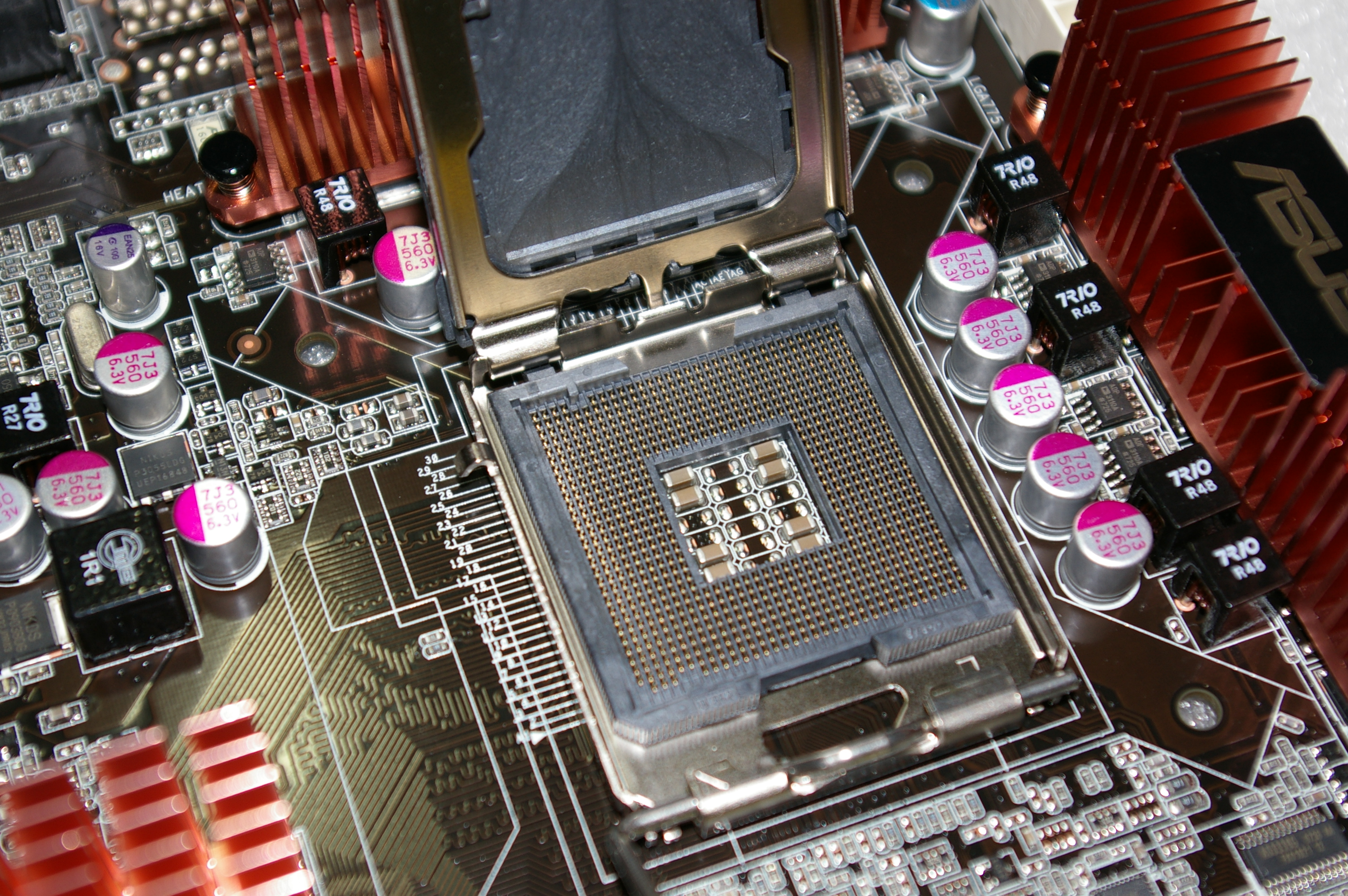
Image thanks to Nao Iizuka
Now take the processor and gently place it inside the socket. Beware! There’s no need to push! The processor will fit its place if you placed it correctly. If you didn’t it will bump out a bit, just rotate it until you find the right position. After that, lock the socket once again.
Step four: mount the power supply
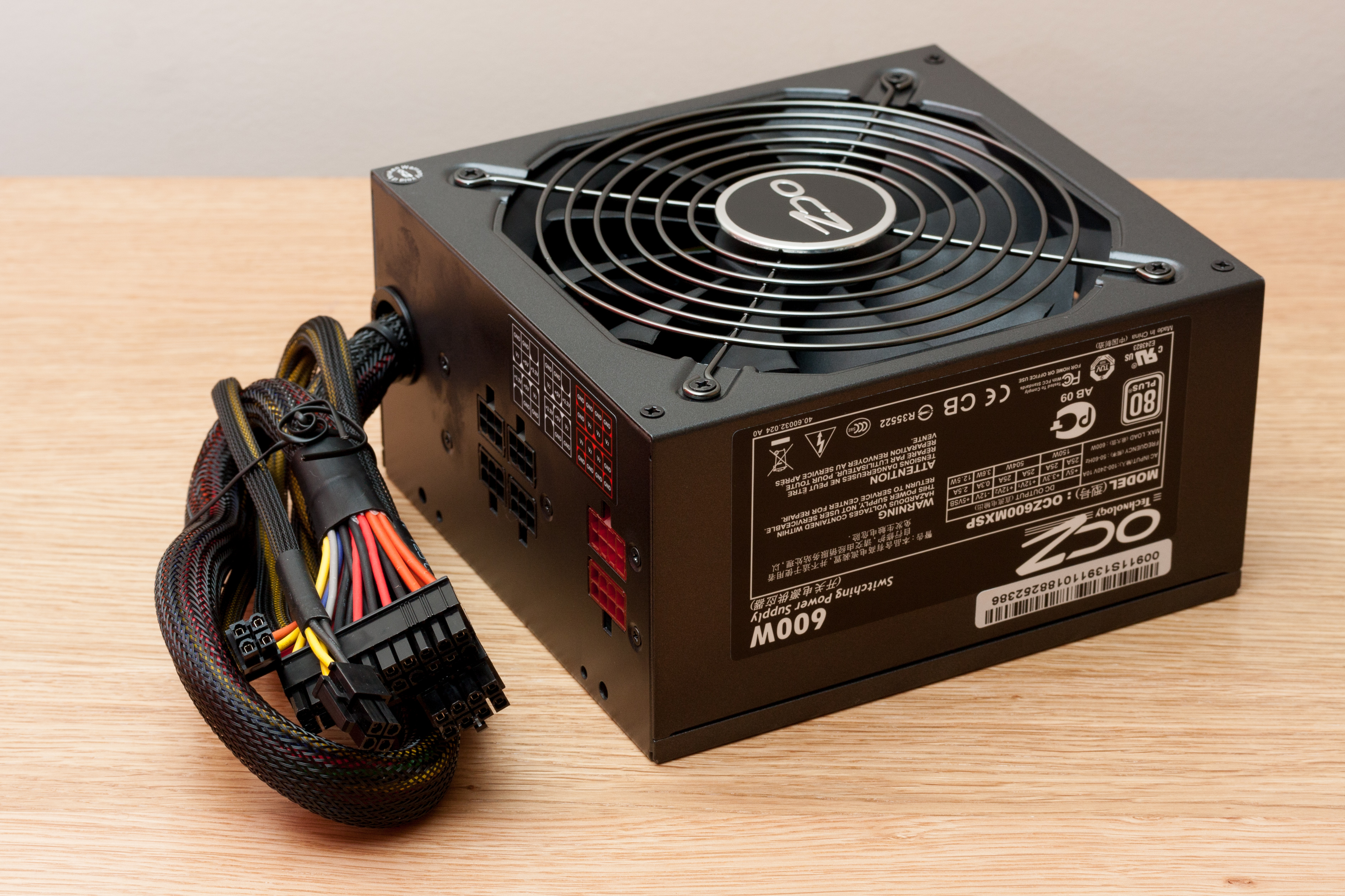
By Danrok (Own work) [CC BY-SA 3.0], via Wikimedia Commons
Step five: mount the graphic card
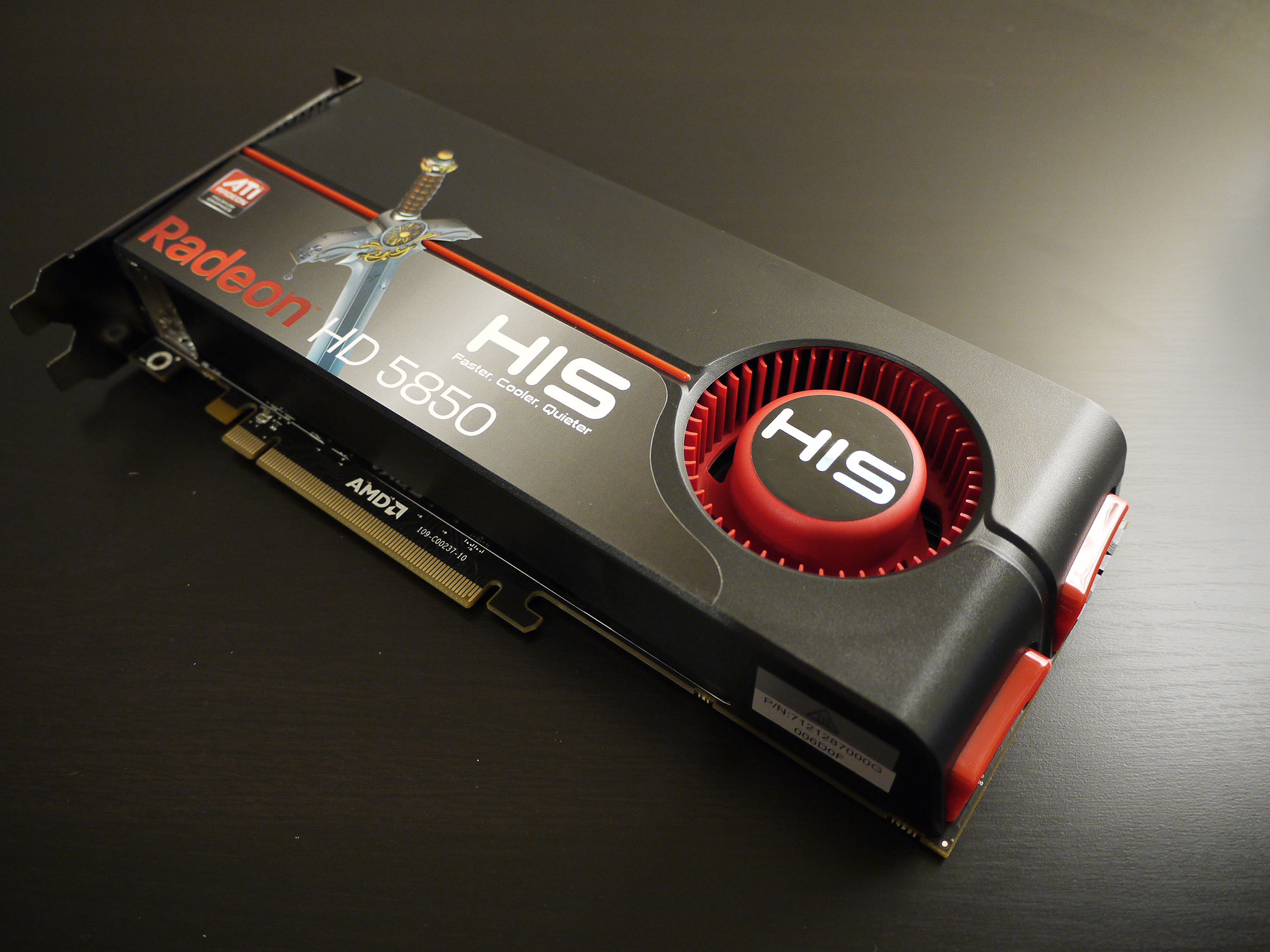
Image thanks to Forrestal_PL
If you have decided to buy and use a graphic card, now it is the time to mount it. On the rear of the case, there will be a metal protection which can be unscrewed/removed by force. Remove the one corresponding to the slot/s where the rear of the card will be. The pins of the graphic card (the gold stripe in the bottom of the photo) has to go on the motherboard.
Step six: mount the RAM
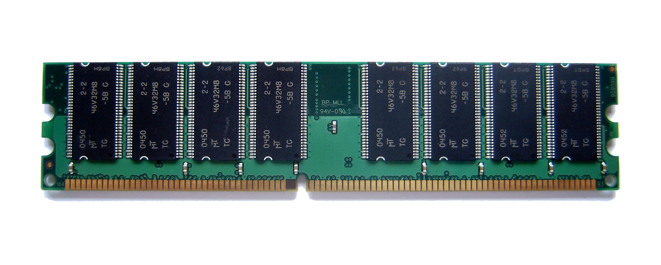
By Utente:Sassospicco (Own work) [CC BY-SA 2.5], via Wikimedia Commons
Step seven: mount disks and drives
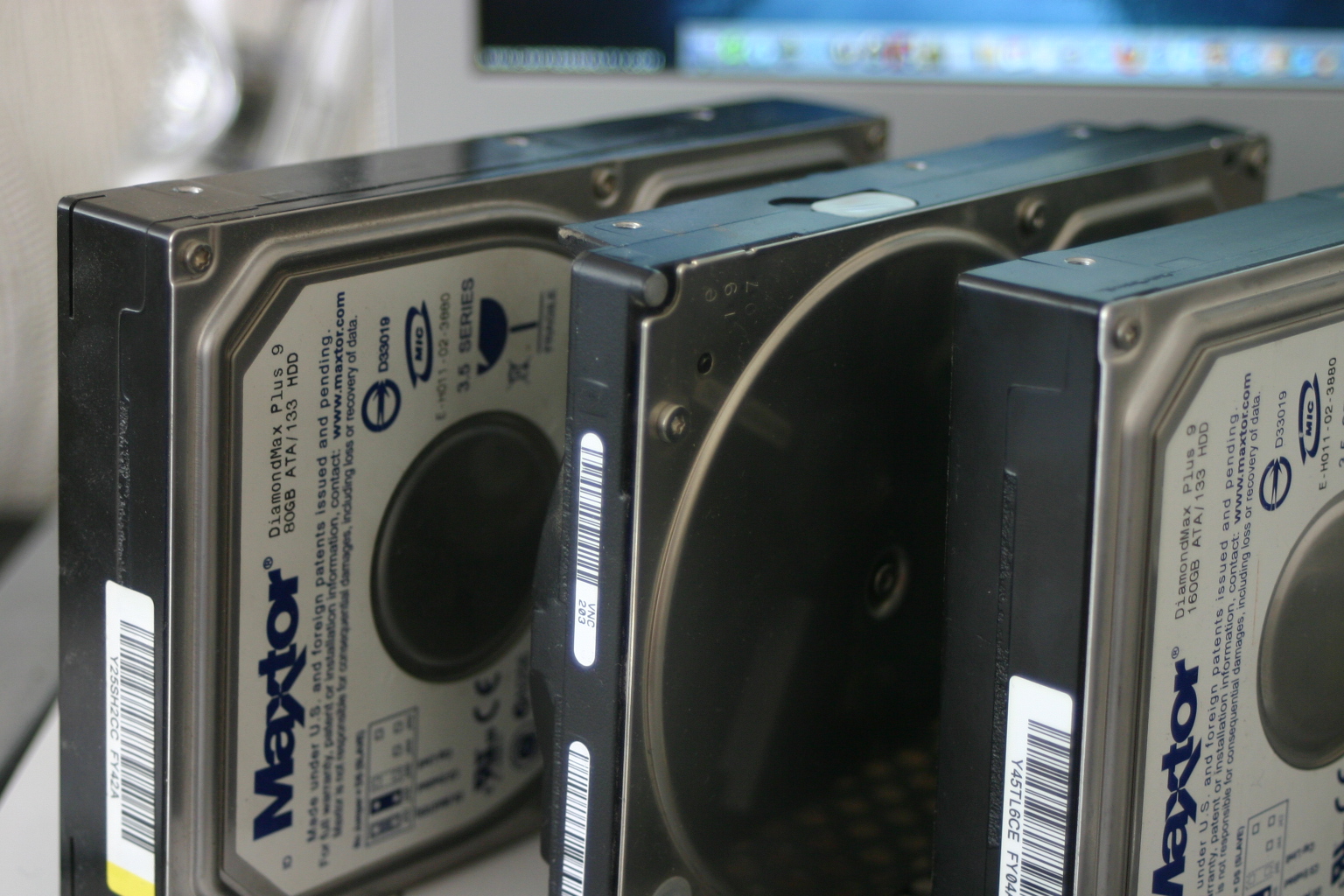
Image courtesy of William Warby.
You will most likely have bought at least one disk. Mounting disks used to be the same for all the cases, but most new cases stray from tradition to offer better placing. Refer to the manual to know where to mount yours. It usually involves either: locking with a mechanism or using screws to fix the drive. The same apply to optical drives/card readers, these however have to be put in another part of the case, usually facing the front panel.
Step eight: mount the heat sink
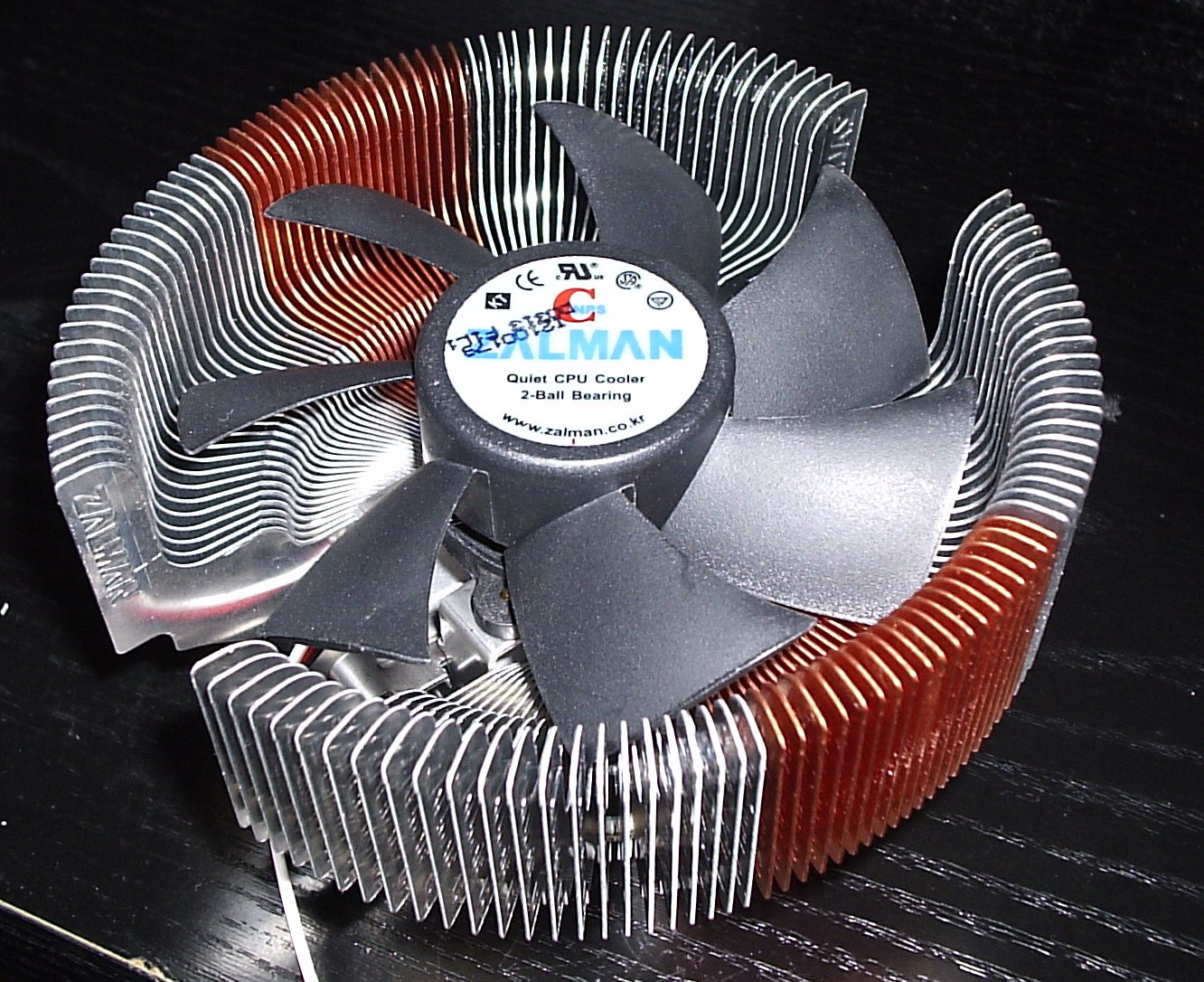
Image thanks to Mike Babcock
This step is the most difficult in my opinion. Mounting a heat sink can be daunting, however with the help of the manual which is mandatory in this case, you will have less problems. Do not apply the thermal grease yet, do it only when you’re sure you know how to mount the heat sink. In many cases (mostly when you don’t use the stock heat sink), you will have to mount a back panel, in the rear of the motherboard. When you’re ready, eventually placed the back panel, apply the thermal grease on the processor, and on top of that place the heat sink. Now lock it with screws or with its mechanism.
Step nine: connecting things up
Now the last step before closing up everything. Connections may be a difficult task for newbies, but don’t worry it’s simpler than you might imagine.
Motherboard and heat sink
First connect the motherboard to the power supply. You can’t be wrong, it is the connector in the picture:
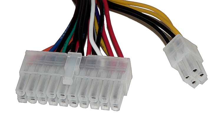
By Baran Ivo (Own work) [Public domain], via Wikimedia Commons
Disk & Drives
Now we have to point a difference disk and drives can have different connectors, you will most likely have one of these:
IDE: older, bigger and slower
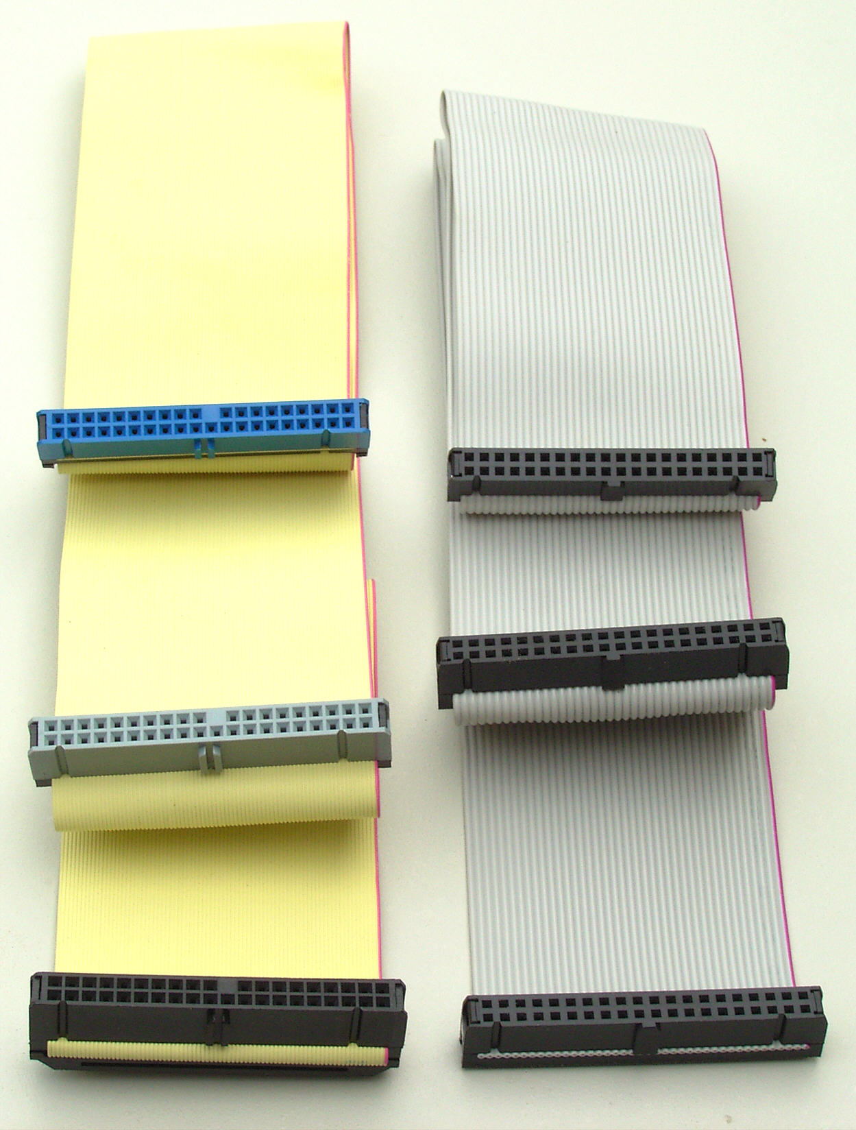
By User Smial on de.wikipedia (Own work) [FAL, GFDL 1.2 or CC BY-SA 2.0 de], via Wikimedia Commons
To power one of these devices you will usually need a Molex connector. The one shown in the next picture.
IDE drives are old and many motherboards won’t even have an IDE connector, so be careful.
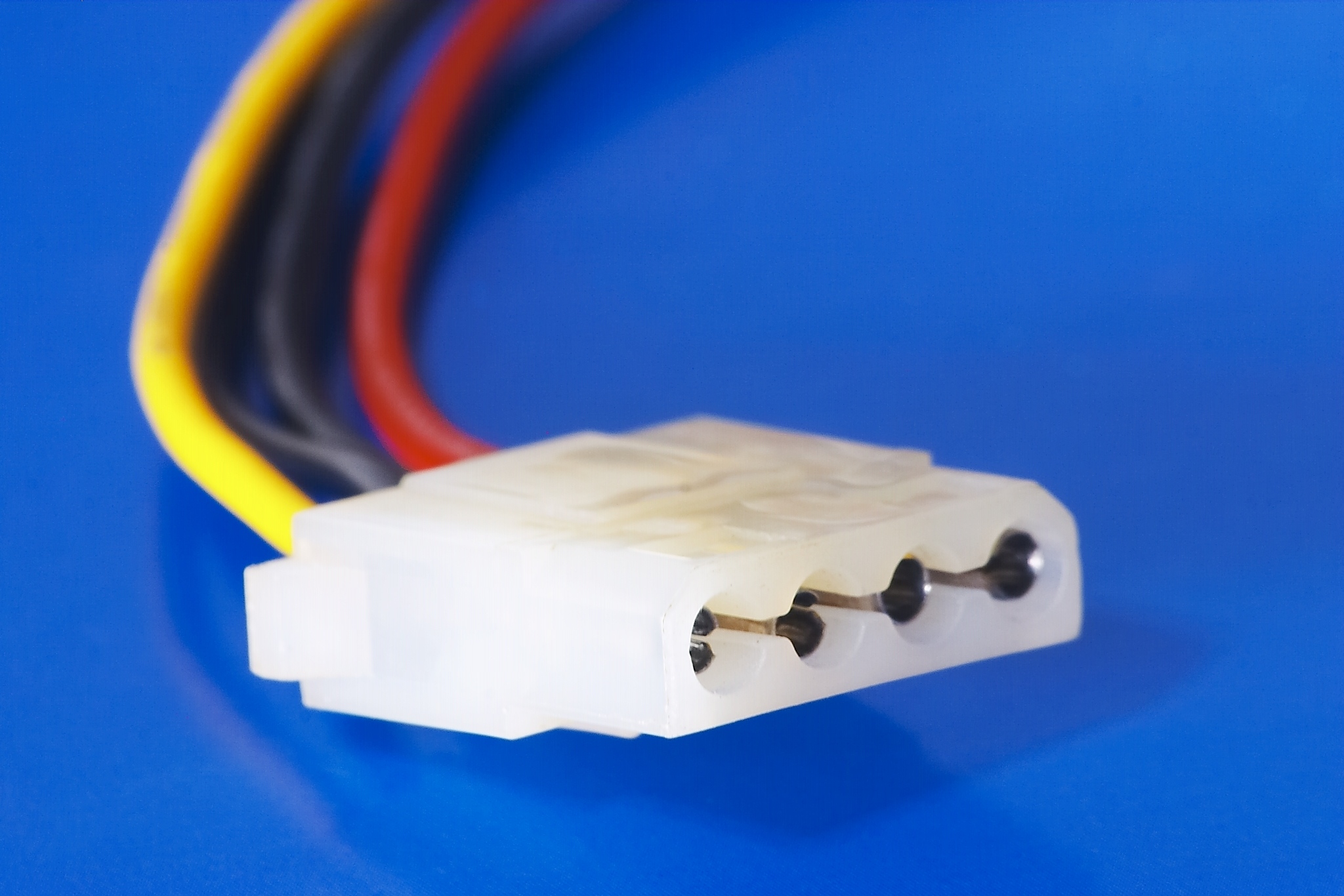
By w:es:Usuario:Barcex (Own work) [CC BY-SA 2.5], via Wikimedia Commons
SATA: newer, smaller and faster

By en:User:Berkut [GFDL or CC-BY-SA-3.0], via Wikimedia Commons
SATA devices have smaller cables and boast an enormous performance compared to IDE devices. They are the most common type of device in desktops nowadays.
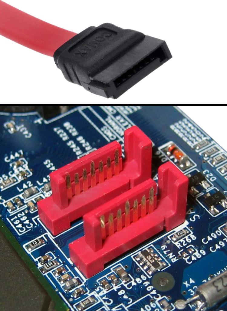
By en:User:Berkut [GFDL or CC-BY-SA-3.0], via Wikimedia Commons
One SATA connector is used for one device unlike IDE cables.
To power it you use a SATA power cable, shown below.
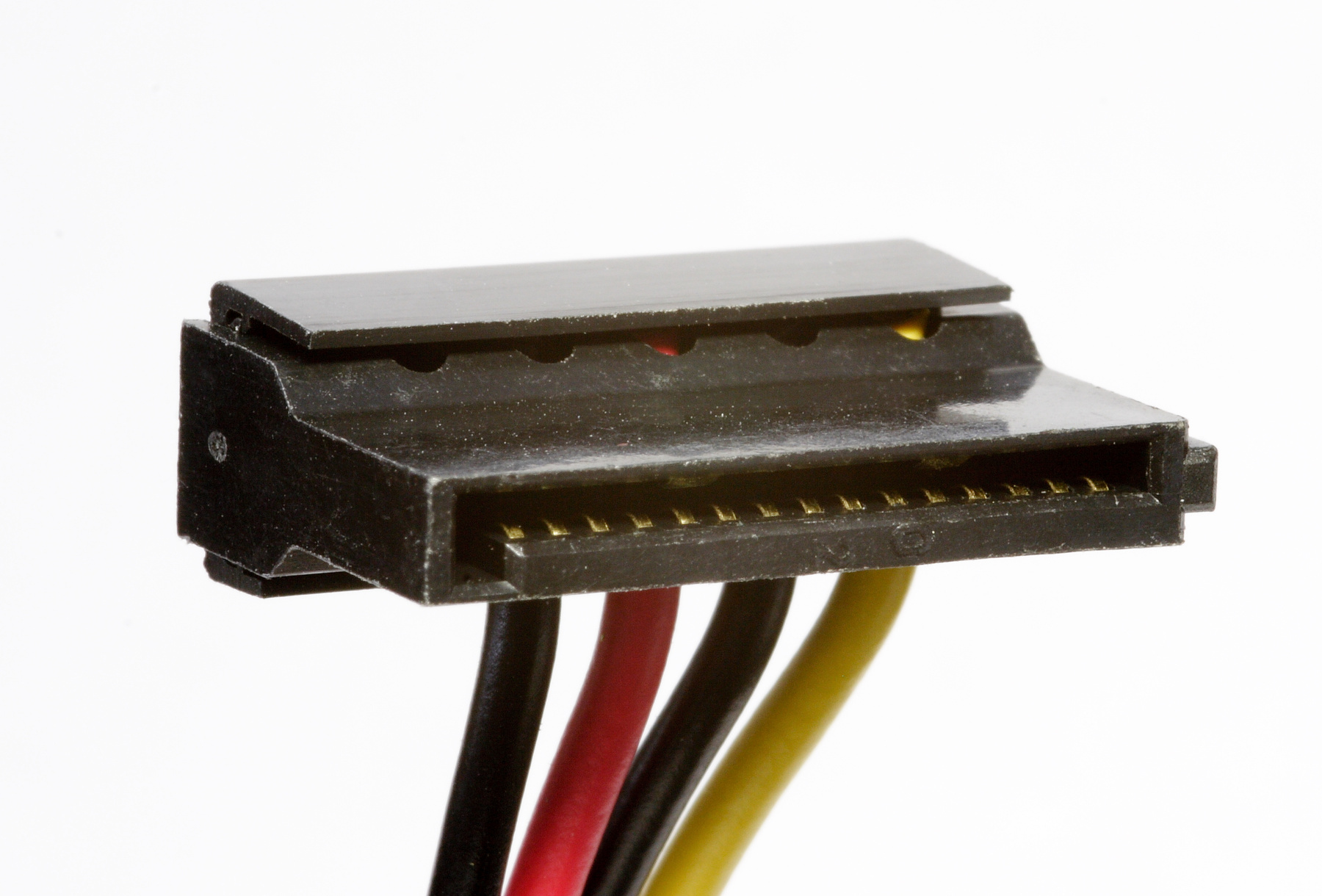
By Afrank99 (Own work) [CC BY-SA 3.0], via Wikimedia Commons
Plus: GPU connector
Some powerful graphic cards might require more power, and have one or two power plugs with 6-8 pin. Some power supply won’t have these cables and thus require adaptors.
Power buttons
Now the hard part: connecting the front panel to the motherboard. Unfortunately I can’t help you much in this part, many motherboards have a slightly different layout, refer to the manual to know more. It usually comprises four couples of wires.
Closing the case
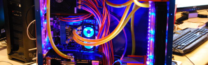
If you followed correctly all the steps and connected everything, now you have everything set up however, be sure to double check before closing everything. Now, plug the power and try to boot up for the first time. If you hear the speaker beep more than one time you’ve done something incorrectly or a component might be damaged. But if the computer boots and you can see some images on the screen, well you’re ready for the next steps.
Stay tuned for the third and last article in this series: installing the operating system.
Image thanks to Dave Monk.
- 2020 A year in review for Marksei.com - 30 December 2020
- Red Hat pulls the kill switch on CentOS - 16 December 2020
- OpenZFS 2.0 released: unified ZFS for Linux and BSD - 9 December 2020

Recent Comments